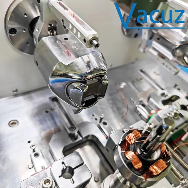
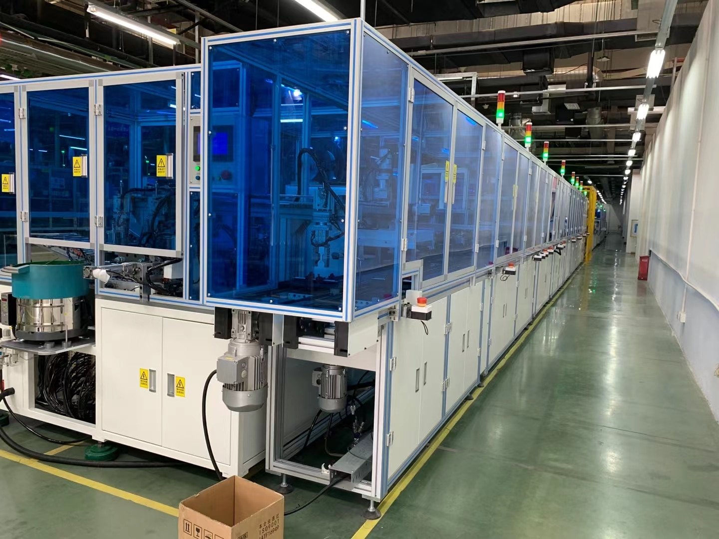
The stator and rotor assembly of a brushless DC motor is the lifeblood of motor manufacturing. Assembly precision plays a crucial role in determining the motor’s efficiency, noise level, and service life. This assembly process must adhere to rigorously high mechanical, electrical, and process standards and proceed in an orderly manner according to standardized procedures. Below, Vacuz will briefly explain this process!

I. Analysis of the Core Requirements for Stator and Rotor Assembly
Mechanical Precision:
1. Stator-Rotor Gap (Air Gap): The uniformity of the air gap and its adherence to the designed value are crucial, typically within a design range of 0.1-1mm. Excessively large air gaps significantly increase magnetic resistance, leading to a significant decrease in motor efficiency. Excessively small air gaps can cause friction between the rotor and stator, a phenomenon known as “braking.” Accurate air gap control requires the use of high-precision tooling, such as air gap gauges and laser measuring instruments, and precise adjustments to the stator core or rotor shaft installation position.
2. Coaxiality: The coaxiality between the rotor shaft and the stator inner bore must be strictly controlled to ≤ 0.02mm. Otherwise, the motor will produce severe vibration and harsh noise during high-speed rotation. To achieve this requirement, precision bearings and a high-rigidity base are required. Dynamic balancing, such as weight removal or counterweighting, can further optimize performance.
3. End-face Parallelism: The end-face parallelism between the stator and rotor must be ≤ 0.05mm to prevent magnetic circuit asymmetry, which can lead to reduced efficiency and electromagnetic noise.
4. Electrical Performance: Meticulous Control
5. Insulation Resistance: The insulation resistance between the stator winding, the core, and the housing must be ≥ 100MΩ at 500V DC. This is a critical barrier to preventing leakage and short circuits. To achieve this, high-temperature resistant insulating materials, such as polyimide film, must be used, and the components must be varnished and dried before assembly.
6. Turn-to-Turn Insulation: Winding turns must remain intact, free of damage or burrs, to withstand high-voltage pulses. Automatic winding machines can effectively minimize human damage, and inter-turn impulse voltage tests (e.g., 3000V/1s) are then rigorously verified.
7. Magnetic Pole Alignment: The rotor magnets and stator slots must be precisely aligned, with an error of ≤ 1° electrical angle. Failure to do so will result in torque ripple and reduced efficiency. Use encoders or Hall sensors for positioning, and servo motors for high-precision alignment.
Process Stability:
1. Cleanliness: The assembly environment must meet Class 10,000 cleanliness standards to prevent dust and metal shavings from entering the air gap, causing wear or short circuits. Assembly in a cleanroom equipped with an air shower and dust removal equipment is essential.
2. Temperature Control: Processes such as varnishing and drying have extremely strict temperature requirements, requiring control between 120°C and 150°C to prevent insulation aging and winding deformation.
3. Consistency: During mass production, the fluctuation of each motor’s parameters (such as air gap, resistance, and inductance) must be within ±5% to ensure consistent product performance.
II. Detailed Explanation of the Standard Stator and Rotor Assembly Process
Preparatory Work: Rigorous Material and Tooling Inspection
Material Inspection: Detailed inspection of key components, including the stator core (check for deformation and burrs), rotor magnets (ensure uniform magnetic properties), and windings (check for open circuits and short circuits). For example, a magnetometer is used to measure the rotor’s residual magnetism to ensure it meets the design value of 1.2-1.4T.
Tooling Preparation: Specialized tools such as air gap gauges, dynamic balancing machines, press-fit dies, and laser alignment tools are available to provide strong support for subsequent assembly.
Stator Pretreatment: Shaping and Insulation Strengthening
Winding Shaping: Use a shaping tool to flatten the winding ends to ensure they do not interfere with the housing during assembly.
Varnishing and Drying: The stator is dipped in insulating varnish (such as epoxy resin) and then dried (120°C/4 hours) to enhance insulation and mechanical strength.
Rotor Pretreatment: Magnet Fixing and Dynamic Balancing Optimization
Magnet Bonding/Injection Molding: For surface-mount rotors, the magnets are bonded to the rotor core surface using a high-strength adhesive (such as epoxy structural adhesive) and reinforced in a curing oven (80°C/2 hours). For embedded rotors, the magnets are embedded in the core using injection molding to prevent them from falling out during high-speed operation.
Dynamic Balancing: The rotor is mounted on a dynamic balancing machine, and the imbalance is measured (e.g., ≤ 0.5g·cm). Correction is performed by removing weight (drilling) or adding counterweights (welding balancing blocks).
Stator and Rotor Assembly: Accurate Adjustment and Secure Installation
Air Gap Adjustment: Slowly insert the rotor into the stator bore. Use an air gap gauge to measure the clearance around the rotor. Adjust the axial position of the stator or rotor (e.g., by adding shims) to achieve a uniform air gap.
End Cover Pressing: Use a hydraulic press to press the front and rear covers into the stator, maintaining a pressure between 10 and 50 kN to prevent deformation of the end covers.
Bearing Installation: Press the bearings onto the rotor shaft using a shrink fit process (heating the bearings to 80-100°C) or a cold press process, ensuring the fit clearance meets the design requirement of 0.01-0.03 mm.
Final Inspection and Testing: Comprehensive Troubleshooting and Performance Verification
Mechanical Inspection: Manually rotate the rotor to check for binding or abnormal noise. Use a laser alignment tool to check the rotor shaft for radial runout (≤ 0.02 mm).
Electrical Testing: Insulation resistance test (≥ 100MΩ at 500V DC) and withstand voltage test (no breakdown at 1800V AC/1s).
Performance Testing: No-load current, speed, torque, and other parameters are tested on a motor test bench to ensure compliance with design specifications.
III. Common Problems and Solutions
1. Uneven Air Gap
Cause: Deformed stator core or bent rotor shaft.
Solution: Straighten the rotor shaft or use elastic washers to adjust the stator position.
2. Rotor Dynamic Balancing Exceeds Tolerance
Cause: Magnet attachment offset or uneven injection molding.
Solution: Reattach the magnets or optimize the injection molding process.
3. Winding Insulation Failure
Cause: Insufficient varnishing or excessive humidity.
Solution: Increase the number of varnishing cycles or assemble in a dry environment.

What are the requirements for assembling the stator and rotor of a brushless DC motor? What processes should be mastered? Vacuz has provided a brief explanation above. We hope this little knowledge can help you!
E-Mail: sales@vacuz.com [fusion_form form_post_id="431″ margin_top="" margin_right="" margin_bottom="" margin_left="" hide_on_mobile="small-visibility,medium-visibility,large-visibility" class="" id=""][/fusion_form]

