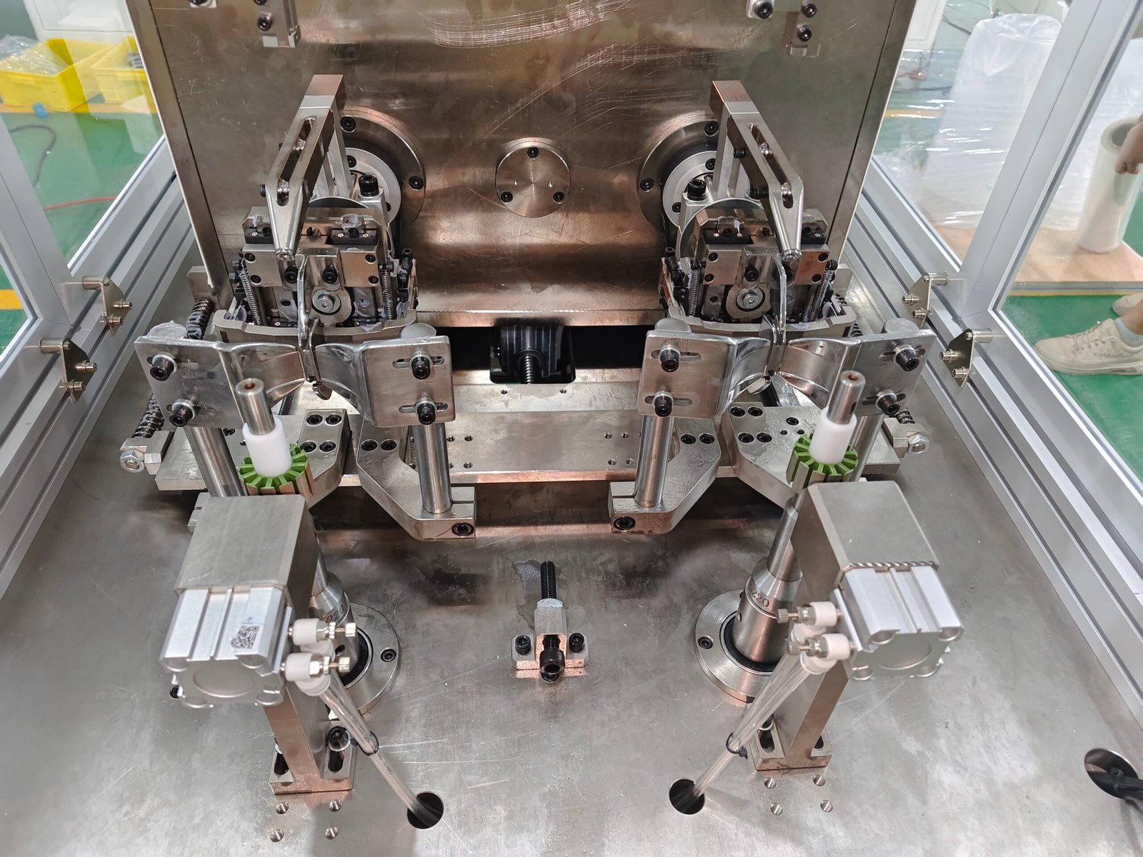
In brushless motor stator winding machines, the precision, material, structure, and adjustment requirements of the nozzle and die directly affect the winding quality and equipment stability. What are the specific requirements? Vacuz will give you a brief introduction below! We hope this will be helpful!

I. Technical Requirements for the Nozzle
1. Material and Wear Resistance
The nozzle must be made of high-hardness, wear-resistant materials (such as cemented carbide or ceramic) to reduce wear caused by long-term friction and prevent wire breakage or uneven wire routing due to nozzle deformation.
The surface must be polished to ensure uniform resistance when the wire passes through, preventing scratches on the wire insulation layer.
2. Size and Wire Diameter Matching
The inner diameter of the nozzle must be accurately designed according to the wire diameter, usually 0.02-0.05mm larger than the wire diameter, to reduce friction and prevent wire wobble.
For example, when winding 0.1mm fine wire, the recommended inner diameter of the wire nozzle is 0.12-0.15mm; when winding 1.0mm thick wire, the inner diameter needs to be increased to 1.05-1.1mm.
3. Structure and Wire Laying Method Compatibility
Fork-type external winding machine: The wire nozzle needs to be fixed to the end of the fork and rotate at high speed with the fork (speed can reach 2800+ RPM). Therefore, a lightweight design is required to reduce the impact of centrifugal force while ensuring rotational stability.
Needle-type internal winding machine: The wire nozzle is installed at the front end of the needle bar and needs to move up and down synchronously with the needle bar (speed can reach 800-1000 RPM) and move back and forth. Therefore, a high-rigidity structure is required to prevent wire laying deviation caused by vibration.
4. Dynamic Performance Optimization
The wire nozzle needs to work in conjunction with the tension control system to ensure that wire tension fluctuations are controlled within ±3% during high-speed start-up, stop, or speed changes, avoiding wire breakage or loosening due to sudden tension changes.
II. Technical Requirements for the Die
1. Precision and Machining Process
The die must be machined with high precision, ensuring that the slot size and positional error are ≤0.01mm to avoid wire jamming or misalignment due to die errors.
The die surface must be polished to Ra≤0.8μm to reduce friction between the wire and the die, preventing scratches or burrs.
2. Structure and Stator Compatibility
External winding die: Must fit tightly with the stator slot. The die tongue must be designed as a retractable structure to hold the slot before winding and retract after winding, preventing damage to the wire.
Internal winding die: Must accurately match the stator inner diameter. The die movement trajectory must be synchronized with the needle bar movement trajectory to ensure accurate wire winding into the slot.
3. Wear Resistance and Lifespan
The die must be made of high-hardness material, achieving a hardness of HRC58-62 after heat treatment to withstand long-term high-speed friction.
Regularly inspect the die for wear. Replace the die promptly when the slot size increases by more than 0.05mm or the surface roughness deteriorates to avoid affecting wire routing accuracy.
III. Requirements for Coordinated Adjustment of Nozzle and Die
1. Initial Positioning Calibration
Use a laser rangefinder to calibrate the die installation position, ensuring the first turn positioning error is ≤0.01mm. For example, when winding a 6-slot stator, the die needs to be moved in 6 steps controlled by the program, with each step’s positioning verified by sensor feedback.
Adjust the relative position of the nozzle and die to ensure the nozzle centerline coincides with the die slot centerline, with a deviation ≤0.05mm, to prevent wire misalignment leading to uneven wire routing.
2. Dynamic Adjustment and Parameter Optimization
Speed Gradient Test: Gradually increase the speed from a low speed (e.g., 200RPM) to the rated speed (e.g., 1000RPM), increasing by 10%-20% in each increment, running for ≥10 minutes, and checking the wire routing neatness. If the overlap rate exceeds 0.2%, adjust the die movement speed or nozzle tension.
Tension Compensation Function: The tension is preset based on the wire’s elastic modulus (e.g., 0.5-1.2N for 0.1mm copper wire) and a speed-tension mapping model is established.
Troubleshooting and Maintenance
If wire breakage or damage occurs, check for wear on the inner diameter of the wire nozzle, roughness of the die groove, or positioning misalignment. For example, frequent wire breakage during winding of 0.2mm diameter wire may be due to excessive friction caused by an enlarged inner diameter of the wire nozzle to 0.25mm, requiring nozzle replacement.
Regularly clean the wire nozzle and die to remove wire residue (such as copper shavings or insulating varnish) to prevent accumulation and hinder wire winding. It is recommended to clean once per shift using a lint-free cloth dampened with alcohol.

What are the requirements for the wire nozzle and die of a brushless motor stator winding machine? What are the technical details? Vacuz has provided a simple explanation above; we hope this information is helpful!
