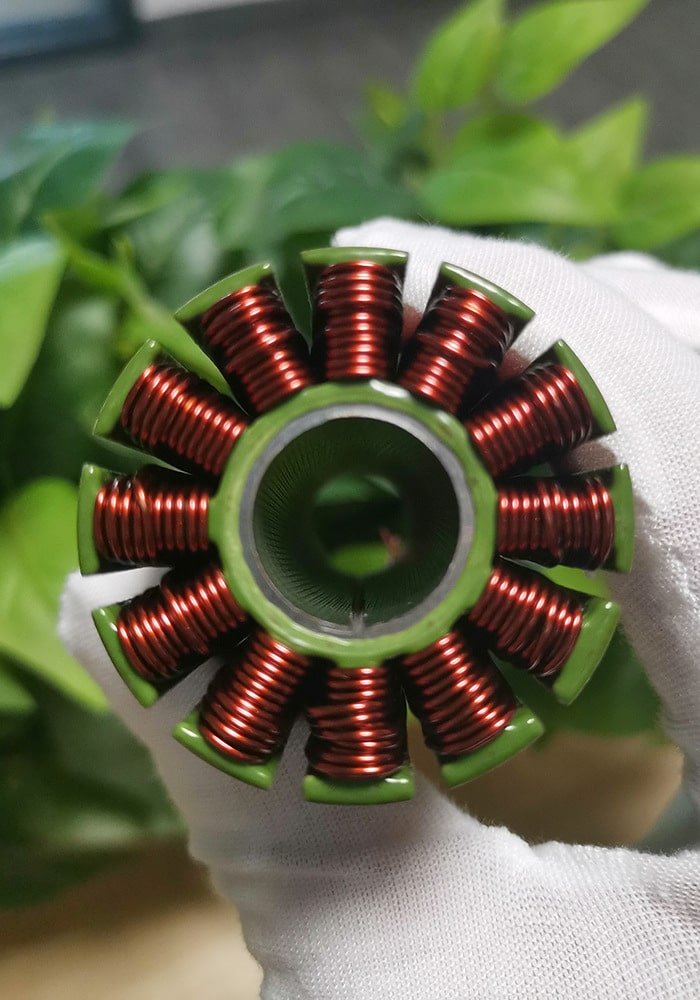
The debugging of a fully automatic precision winding machine generally revolves around equipment precision, parameter matching, hardware configuration, and operating procedures. But what are the specifics? Vacuz will briefly introduce this below! We hope it will be helpful!

I. Core Debugging Technical Requirements
1. Equipment Precision Assurance
Mechanical Component Precision: The machining and assembly precision of components such as the frame, guide rails, and lead screws must meet requirements to ensure the wire remains straight during winding and avoids wire deviation due to equipment vibration or gaps.
Die Matching: The width and height of the die must fit tightly with the winding rod. Too tight a fit will affect loading and unloading efficiency, while too loose a fit will cause the die to wobble, affecting the neatness of the wire arrangement. The die precision must be checked regularly, and severely worn dies should be replaced promptly.
2. Tension Control System Optimization
Tension Range Setting: Adjust the tension value according to the wire material (copper wire/aluminum wire) and wire diameter. Because aluminum wire is easily stretched, the tension correction value must be greater than that of copper wire (approximately +0.02mm for copper wire, +0.02~0.2mm for aluminum wire). Excessive tension may cause wire breakage or a reduction in the actual winding diameter, while insufficient tension will result in coil swelling and messy wiring.
Dynamic Adjustment Function: The equipment must have real-time tension feedback capability, automatically adjusting the tension based on winding speed and wire strength to avoid sudden tension changes during start-up/stop.
3. Precise Setting of Winding Parameters
Basic Parameters: These include the number of coil turns, wire diameter, winding width, wiring spacing, and speed. The wire diameter setting error must be controlled within ±0.01mm. The wiring spacing is usually consistent with the wire diameter, but can be fine-tuned for special processes.
Speed and Direction Control: The winding speed needs to be set according to the wire strength and bobbin shape. It is recommended to start with a medium speed (e.g., 500~1000rpm) and gradually increase the speed to a stable value. The winding direction (clockwise/counterclockwise) must be consistent with the process requirements to avoid pin collisions or skipped wires.
Buffer Time Setting: The buffer time for start-up and stop must be reasonable to avoid tension fluctuations caused by mechanical impact. It is generally set to 0.5~2 seconds.
4. Hardware Configuration and Auxiliary Functions
Wire Laying Device Accuracy: Components such as the wire laying guide rollers and wire nozzles must be accurately positioned and conform to the mold. Adjustments can be made gradually through full-winding testing until the wire laying meets requirements.
PLC Servo Drive: Select a high-precision controller to ensure the stability of control over parameters such as winding position, speed, and tension, avoiding uneven wire laying due to data errors.
Safety Protection Functions: The equipment must be equipped with safety functions such as an emergency stop button, overload protection, and wire breakage detection to prevent operational accidents.
II. Debugging Precautions
1. No-Load Test and Pre-Inspection
Before debugging, check the worktable, mold fixtures, and transmission range for debris; verify the power connection is correct; and ensure the wire spool position, wire frame, wire guide rollers, tensioner, and other components are intact.
The no-load running speed should be slow (e.g., 100~200 rpm) to observe whether the equipment operates smoothly and whether there is any abnormal noise or vibration.
2. Phased Debugging Process
Manual Mode Testing: Perform a small-scale winding (e.g., 1-2 turns) to observe the uniformity of the wire arrangement, tension stability, and the relative position of the needle rod and the die, preventing needle collisions or skipped wires.
Automatic Mode Verification: After passing the manual test, switch to automatic mode to complete the entire winding process and check if the product meets specifications (e.g., coil diameter, wire density).
Pre-Mass Production Confirmation: Wind 3-5 samples consecutively, perform a pinhole test (ensuring leakage current meets standards) and visual inspection, confirming there are no broken or overlapping wires before proceeding with mass production.
3. Common Problem Troubleshooting
Uneven Wire Arrangement: Check wire quality (wire diameter uniformity, insulation integrity), tension control, wire arrangement device accuracy, and PLC parameter settings.
Broken or Damaged Wire: Adjust the tension value, reduce the winding speed, and check for jamming or sharp edge friction in the wire path.
Die Vibration: Re-tighten the die and adjust the clearance between the die and the winding rod to ensure there is no looseness.
4. Operator Training
Installation personnel must be familiar with the equipment manual and master skills such as tension adjustment, parameter setting, and fault code interpretation.
Regular equipment maintenance training should be conducted, including parts replacement, lubrication, and daily cleaning, to extend the equipment’s lifespan.

What are the technical requirements for debugging a fully automatic precision motor stator core winding machine? What issues should be considered? Vacuz has provided a brief explanation above; we hope this information is helpful!

